TinkerCAD Circuits
You will need to have an account on TinkerCAD
and you will need to have logged in.
Follow this link
https://www.tinkercad.com/things/4ojfYB7bjF9 and select the
 button.
Clicking on the  button will allow you write code in
either Text (writing the code) or Blocks (drag and drop like Scratch) format.
button will allow you write code in
either Text (writing the code) or Blocks (drag and drop like Scratch) format.
A block has already been created showing you how to enable the motors (they are enabled in pairs,
the right hand side and the left hand side, if you don't enable them they won't turn) and how to
make each set of motors go forwards and backward.
Click the Code button again to hide the code and then click on the
 button to start your car driving.
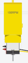
You should see numbers on each of the motors showing you the speed it's going. Minus numbers
indicate that the motors are going in the opposite direction
button to start your car driving.
You should see numbers on each of the motors showing you the speed it's going. Minus numbers
indicate that the motors are going in the opposite direction
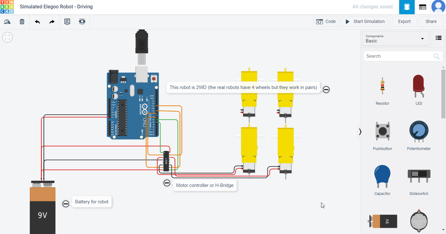
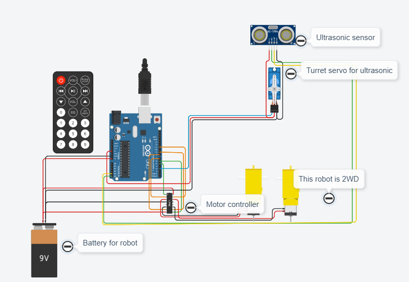
From the Circuit view work out which pin numbers on the Uno board,
relate to which pins on the Motor controller and then to which set of motors. Make a note of the answers.
In the Blocks view change the settings from HIGH to LOW on each of the
motors and see what happens.
In the Blocks view edit the blocks to turn on the motors, drive forward, stop,
reverse and then stop (you might need a pause between them). When you're happy with your code click the download button
 and save your code so that you can send it to us.
In the Blocks view edit the blocks to make the robot go round in a circle. When you're
happy with your code click the download button
and save your code so that you can send it to us.
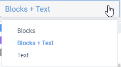
When you're happy with coding using the Blocks view, change to the Blocks + Text view and have a
look at the code you've created. If you select the Block + Text view you can edit the blocks and see how this affects
the code it generates (you can't edit the text in this view though).
Changing to the Text view will allow you to edit the actual code, but it will bring up a warning that your
Blocks layout will disappear.
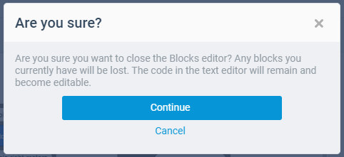
If you then change back to Blocks view or Blocks + Text view, ALL of your
code will disappear and you will have to start again (there is no undo!)
Introducing Arduino Programming
The instructions for our robot are always written inside
Functions.
Some values are defined
above the functions. There are two essential functions for every program
void setup()
and void loop().
When we create a new program it will look like this:
          void setup( )
          {
            // put your setup code here, to run once:
          }
          void loop( )
          {
            // put your main code here, to run repeatedly:
          }
All the instructions in void setup() are run when we first turn on the robot.
This is good for any initialisation we need to do. After that, all the instructions in void loop()
are run in a continuous loop until we turn off the robot. We can define some of our own functions
to help make the code more readable. Text that comes after // is a comment for us that will be
ignored by the robot. Use comments to remind yourself and tell others what the code is doing.
Driving the Robot
The Elegoo is a 4-wheel robot, but the wheels are controlled in pairs. The motors are connected to
numbered pins on the Arduino, so to start with, we need to define which pins are used. For each pair of
wheels we have 3 pins. Digital signals HIGH or LOW are sent to the pins to perform actions. Let's
look at the left wheels. Pin 5 enables the left motors. If this is set to LOW (off) the motors are off.
If it is set to HIGH (on) then we can drive the motors. The driving is then done using pins 7 and 8.
For the wheels to move, one pin needs to be set to HIGH and the other to LOW. If they are both the
same the wheels will not move
Setting them both to HIGH could blow up/damage the motor controller/H-bridge
and your motor - so try not to do it!
- First define the pins above void setup(), and enable the left motors
              #define LeftEnable 5
              #define LeftForward 7
              #define LeftReverse 8
- Next initialise the pins to expect output inside void setup()
              pinMode(LeftEnable, OUTPUT);
              pinMode(LeftForward, OUTPUT);
              pinMode(LeftReverse, OUTPUT);
              digitalWrite(LeftEnable, HIGH); //Enable left motor
- Below the loop function, we're going to create three functions to turn the left wheels forward,
reverse and stop. The first function is given as an example, replace the ?????s in the second
and third to match the function names.
digitalWrite means we want to send a digital signal to whatever is inside this function.
LeftForward is the pin we would like the digitalWrite to act on.
HIGH is what we would like the pin to do.
Digital signals work on 1s and 0s, 1 being on (HIGH) and 0 being off (LOW).
In our case, 1 will be go and 0 will be stop.
Remember you should never have both pins on (HIGH) at the
same time so you should always write your code so that the pin you are turning off (LOW) goes first.
              void setLeftForward()
              {
                digitalWrite(LeftReverse, LOW); //Left wheel turning forwards
                digitalWrite(LeftForward, HIGH);
              }
              void setLeftReverse()
              {
                digitalWrite(LeftForward, ?????); //Left wheel turning backwards
                digitalWrite(LeftReverse, ?????);
              }
              void setLeftStop()
              {
                digitalWrite(LeftReverse, ?????); //Left wheel stopped
                digitalWrite(LeftForward, ?????);
              }
- Inside the loop function, we are going to call our new functions to drive forward, stop, drive back
and stop. Between each action, we need to tell the program to pause so we can see the changes,
otherwise they would happen too fast. The pause duration is defined in milliseconds (ms),
and there are 1000 ms in a second.
              setLeftForward();
              delay(500);	//pause 500ms
              setLeftStop();
              delay(500);
              setLeftReverse();
              delay(500);
              setLeftStop();
              delay(500);
- Click the Code button to hide the code and then click the Start Simulation button
so that you can see what is happening.
- Given the pins defined below, edit your code to drive the right wheels, based on steps 1-4.
              #define RightEnable 6
              #define RightForward 11
              #define RightReverse 9
- Currently we are just driving one pair of wheels at a time. If we want to go straight, we
need to control both pairs of wheels. Calling the functions like we did in step 4,
create and fill in the functions below.
              void setForward()
              {
                ?????
              }
              void setReverse()
              {
                ?????
              }
              void setStop()
              {
                ?????
              }
Setting left forward and right forward without a pause between will
enable the robot to drive straight.
- Test out these new functions by calling them in the loop function. When you're happy with your
code and you've tested it in the Simulator download it and send it to us.
Write the code to make your robot drive in a square, when completed
download the code and send it to us.
Write the code to make your robot do a
funky dance, when complete download the code and send it to us.
Controlling motor speed
Sometimes we want the robot to travel slower, to do this we can also control the speed of
the motors by reducing the amount of voltage getting to the motors. To do this we can
create another function called void setForwardSpeed()
          void setLeftForwardSpeed()
          {
            analogWrite(leftEnable, 255); //Left wheel speed
            digitalWrite(LeftForward, HIGH);
            digitalWrite(LeftReverse, LOW); //Left wheel turning forwards
          }
          void setLeftReverseSpeed()
          {
            analogWrite(leftEnable, 255); //Left wheel speed
            digitalWrite(LeftForward, ?????);
            digitalWrite(LeftReverse, ?????);//Left wheel turning backwards
          }
          void setLeftStop()
          {
            analogWrite(leftEnable, 0); //Left wheel speed
            digitalWrite(LeftForward, ?????);
            digitalWrite(LeftReverse, ?????); //Left wheel stopped
          }
analogWrite means we want to send a analogue signal to whatever
is inside this function. LeftEnable is the pin we would like the analogWrite to act on.
255 is what we would like the pin to do. Analogue signals work between 0 and 255,
0 being off (LOW), 255 being on (HIGH). In our case, 255 will be full speed and 0 will be stop.
Try changing the speed for each motor.
What would be the benefit of changing the speeds of the motors?
Reacting to Obstacles
In this section we’ll learn how to use the ultrasonic sensor to avoid obstacles.
Follow this link
https://www.tinkercad.com/things/8kZj0L3fcKF-simulated-elegoo-robot-obstacle-avoidance
and select the button.
Aligning the servo
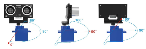
A servo is a small motor which can measure the amount the shaft has turned. In our case we will want to
know how far the servo has turned in degrees. The servo has a range from 0°to 180°. When it is at 90°
, it should be pointing straight forward.
Create a new program with the code below to set the servo postion.
              #include <Servo.h> // library required for interacting with servo
              Servo myservo;

              void setup()
              {
                myservo.attach(3); //Specify the pin the servo is connected to
                myservo.write(90); // move servos to center position -> 90 degrees
              }

              void loop()
              {
              }
Reading from the sonar
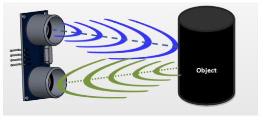
The ultrasound sensor works by sending out high frequency sound ways on one side, and measuring how
long before they are received on the other side. Using this, we can estimate how far away obstacles are. The
side that sends out the signal is typically called the Trigger or trig for short, while the side that receives the
signal is called the Echo.
Remember that all Arduino programs have two parts: the setup which happens once, and is used to set up
anything you need to use in the program. This is where you tell the Arduino which components are wired
up to which pin, and stuff like that. There is also a loop, and the loop is repeated again and again until the
Arduino is turned off (or runs out of battery power).
In the setup function here we need to tell the Arduino which pin has the Trig connection, and which pin
has the Echo connection.
We are going to use the trigger pin to send a message to the sensor from the Arduino (so that is an
OUTPUT pin), but we are going to use the Echo pin to read a message from the sensor (so that is an INPUT
pin).
We are also going to incorporate the servo so we can ‘look’ in different directions with the ultrasonic
sensor. The Servo.h library provides instructions to help control the servo, e.g. allowing us to specify an
angle to turn to.
- At the very top of your program, add the library for the servo and a variable (myservo) we can use to
refer to the servo later on.
                #include <Servo.h> // include the Servo library in the code
                Servo myservo; // create a Servo object called myservo to control the servo
- Define the pins echo and trigger.
                int Echo = A4;  //declare variable Echo as pin A4
                int Trig = A5;  //declare variable Trig as pin A5
- Set them to input and output in the setup function. Note the servo is written slightly differently,
making use of its library.
                void setup()
                {
                    Serial.begin(9600); // Turn on the Serial Monitor output
                    pinMode(Echo, INPUT); // Set pin A4 (Echo) to be an input pin
                    pinMode(Trig, OUTPUT); // Set pin A5 (Trig) to be an output pin
                    myservo.attach(3); // attach servo on pin 3 to servo object
                    myservo.write(90); // move servos to center position -> 90 degrees
                }
- Next, we’ll add a function that will send out a brief signal from the Trigger and measure how
long it takes to come back on the Echo.
                //Ultrasonic distance measurement Sub function which will return a variable of type int
                int Distance_test()
                {
                    digitalWrite(Trig, LOW); // Reset Trigger
                    delayMicroseconds(2);
                    digitalWrite(Trig, HIGH); // Send a signal to Trig
                    delayMicroseconds(20); // Wait 20 micro seconds
                    digitalWrite(Trig, LOW); // Stop signal
                    int Fdistance = pulseIn(Echo, HIGH); // Read from Echo the delay taken for the signal to return from the object
                    Fdistance= Fdistance / 58; // Convert range to cm
                    return (int)Fdistance;
                }
The formula for measuring distance is as follows:
Testing distance = (high level time* velocity of sound (340M/S))/2);
Which gives, delay in microseconds (µS) / 58 = distance in centimeters
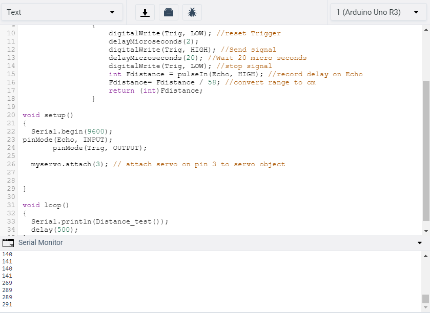
- In the loop, you can now start to obtain readings from the ultrasonic sensor and print them in the serial
monitor by adding the code below. Remember to comment out any other code you may currently
have in the loop function.
              void loop()
              {
                Serial.println(Distance_test());
                delay(500);
              }
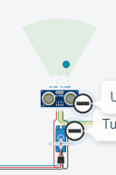
If you click on the ultrasonic sensor in the circuit diagram, you should see a green 'cone' with a
dot in it. The dot is an object in front of the Ultrasonic, you can move this to see how far away or
close it is to the Ultrasonic.
In order to see the figures you will need to turn on the Serial Monitor
at the bottom of the Code window.
What sort of range do you get when you move the dot from top to the bottom
of the cone?
What do numbers 335 and higher mean?
Controlling the Servo
The servo has a range of 180°. Forward is at 90° so we can move it from 0 to 180. Below is
some code that can be added inside the loop function to move the servo all the way from 0° to
180° in 1° steps.
              for (int pos = 0; pos <= 180; pos += 1)
              {
                // goes from 0 degrees to 180 degrees
                // in steps of 1 degree
                myservo.write(pos); // tell servo to go to position in variable "pos"
                delay(20); // waits 20ms for the servo to reach the position
              }
              for (int pos = 180; pos >= 0; pos -= 1)
              {
                // goes from 180 degrees to 0 degrees
                myservo.write(pos); // tell servo to go to position in variable "pos"
                delay(20); // waits 20ms for the servo to reach the position
              }
We are using a programming structure here called a ‘for-loop’. This consists of a counter, a termination
condition and an amount to increment by on each loop. Starting from the initial value (pos=0), the condition
is checked (pos<=180), then if true, the code inside the curly brackets is executed before increasing the
counter by the specified amount (pos+=1). The conidition is then checked again and the block of code with
be repeated until the condition is no longer true.
We start the position of the servo at 0 degrees, if the position is less than or equal to 180 degrees, then
add one degree to the position variable.
Now we have the value 1 in variable ‘pos’, myservo will move 1 degree and wait 20 milliseconds.
Once it has moved 1 degree and waited, the code returns to the top and adds an extra degree to the
position variable and loops this over and over until the position variable reaches 180.
Once the servo reaches 180 degrees, it jumps outside the for loop, then moves along to the next for loop
where it does exactly the same action but in reverse from 180 to 0.
Note: You may need to move the object out of range of the robot to behave as
if the servo was turning to find an object.
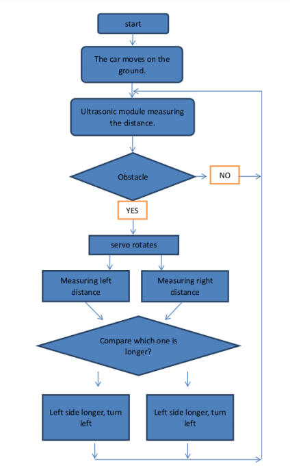
Avoiding obstacles
We now have all the components to drive around whilst avoiding obstacles. The principle is to drive around
until an obstacle is detected. When something gets in the way, we should then use the servo to look left and
right and decide which way to turn before continuing.
Before continuing, think about what needs to be done in each loop. The following section can
be considered as hints for both the planning and implementing.
Reducing speed whilst approaching obstacles
When approaching an obstacle, you may want to slow the robot down to get a more accurate
sensor reading. Can you make some code to slow the robot down the closer it gets to an obstacle?
- In the loop, lets start by adding some variables to record the distances:
int rightDistance = 0, leftDistance = 0, middleDistance = 0;
- Next set the servo to point forward, wait for the movement to complete and then use the distance test
function defined above to get a value for the middle distance.
                  myservo.write(90);
                  delay(100);
                  middleDistance = Distance_test();
- We will now use an if-then-else structure to change the behaviour based on the middle distance.
                  if(middleDistance <= 20)
                  {
                      ?????
                  }
                  else
                  {
                      ?????
                  }
- If there is an obstacle detected, then the first thing we should probably do is stop moving.
If there isn’t an obstacle in the way, we can carry on driving forward.
                  if(middleDistance <= 20)
                  {
                     setStop();
                     delay(500);
                     ?????
                  }
                  else
                  {
                     setForward();
                  }
- In order to decide which direction to turn, we can first turn the servo to obtain readings to the
left and right. We’ll use set positions of the servo, e.g. 20 and 160.
Below is the code for the right, fill in the code for getting the reading
to the left as well. Remember to re-centre the servo after taking the two tests.
                  if(middleDistance <= 20)
                  {
                      setStop();
                      delay(500);
                      myservo.write(20); // Turn the servo to position 20
                      delay(1000);
                      rightDistance = Distance_test();
                      delay(500);
                      ?????
                  }
- Now that we have the readings, we need to compare them and make a decision about which way
to turn the robot. This will use another if-then-else structure. You can adjust the delays so
that your robot turns approximately 90°.
                  if(middleDistance <= 20)
                  {
                        ????? //Code to get the left and right readings
                        if(rightDistance > leftDistance)
                        {
                            setRightForward();
                            delay(360);
                        }
                        else if(leftDistance > rightDistance)
                        {
                            ?????
                        }
                  }
- There is one final condition we should consider. If the readings to the left and right
both indicate obstacles, we may well be in a deadend. In this case, we need to back out or
turn 180° to continue. The condition for checking this is given below, and should be
checked before turning left or right, note the addition of the ’else’ to the following
if-statement. You should fill in what movement you want it to make.
                  if((rightDistance<=20) && (leftDistance <= 20))
                  {
                     ?????
                  }
                  else if(rightDistance > leftDistance)
                  {
                     ?????
                  }
Complete the code to have your robot move around avoiding obstacles,
when you're happy with it send it to us.